Beginning my Arduino Journey
Julia Kaczmarek, 26th December 2025
For the longest time I have wanted to start working with code in a slightly less abstract way and learn more about how electric circuits work. Not to ramble, but since I started learning programming beyond Python syntax, I was very taken aback by just how much is being abstracted the higher the level of language and architecture. It's very interesting to think about what the code is doing at the voltage level, albeit this is again vastly obscured and abstracted when working with Arduino.
Nonetheless, to help with my quest and to satisfy my need for a new tactile hobby, I decided to purchase a starter kit that contains the UNO R3. Because Arduino is very pro-open-source (♡) the board can be replicated by other vendors and it is fully compatible with the Arduino IDE. I went with Elegoo purely because it was cheaper and offered more things. As far as I'm aware the microcontroller they use is the same (ATmega328P) and for my purpose of learning I could not go wrong.
What I have set out to do here
After making my first LED blink and familiarising myself with the Arduino IDE, I wanted to do something kind of myself. The plan was to combine what I learned in lessons 4 and 5 in the Elegoo tutorials, and create a circuit that allows me to control the colour intensity and mixing of my RGB LED with dedicated buttons.
Essential parts
- 1x UNO R3 board
- 1x Breadboard
- 1x RGB LED
- 3x 220Ω resistors
- 3x Push switches (buttons)
- 11x M-M jumper wires
A breadboard is a great hunk of plastic and metal that helps the creation of electrical circuits without the need to solder. A prototyping must, I believe. It's split into two (it has a canyon running across its middle), with the two parts not connected. My board also has 4 extra rows (2 on either side, also called rails) that connect the whole row so you can share a voltage. Where the connection on the rails is horizontal, the connection on the main part is vertical.
The RGB LED has 4 metal prongs, which will be the Red, Green, Blue anodes (connecting to a +) and a cathode (connecting to a -).
The resistors are a requirement for all LEDs if the current that is being supplied is more than milliamperes. This is because LEDs cannot handle the current which is supplied to them, and they burn out instantly. The higher the resistance, the less bright the light (as lesson 3 - the blinking LED - helpfully points out). The current coming out of the digital pins on the board in reality is not that high, so 220Ω is plenty.
Push switches also have 4 metal prongs, but they are 2 walls of two. The switch works by temporarily changing the circuit while the button is actually pressed, allowing (or disallowing, depends whether it's make or break) electricity to flow through the two sides.
Circuit diagram
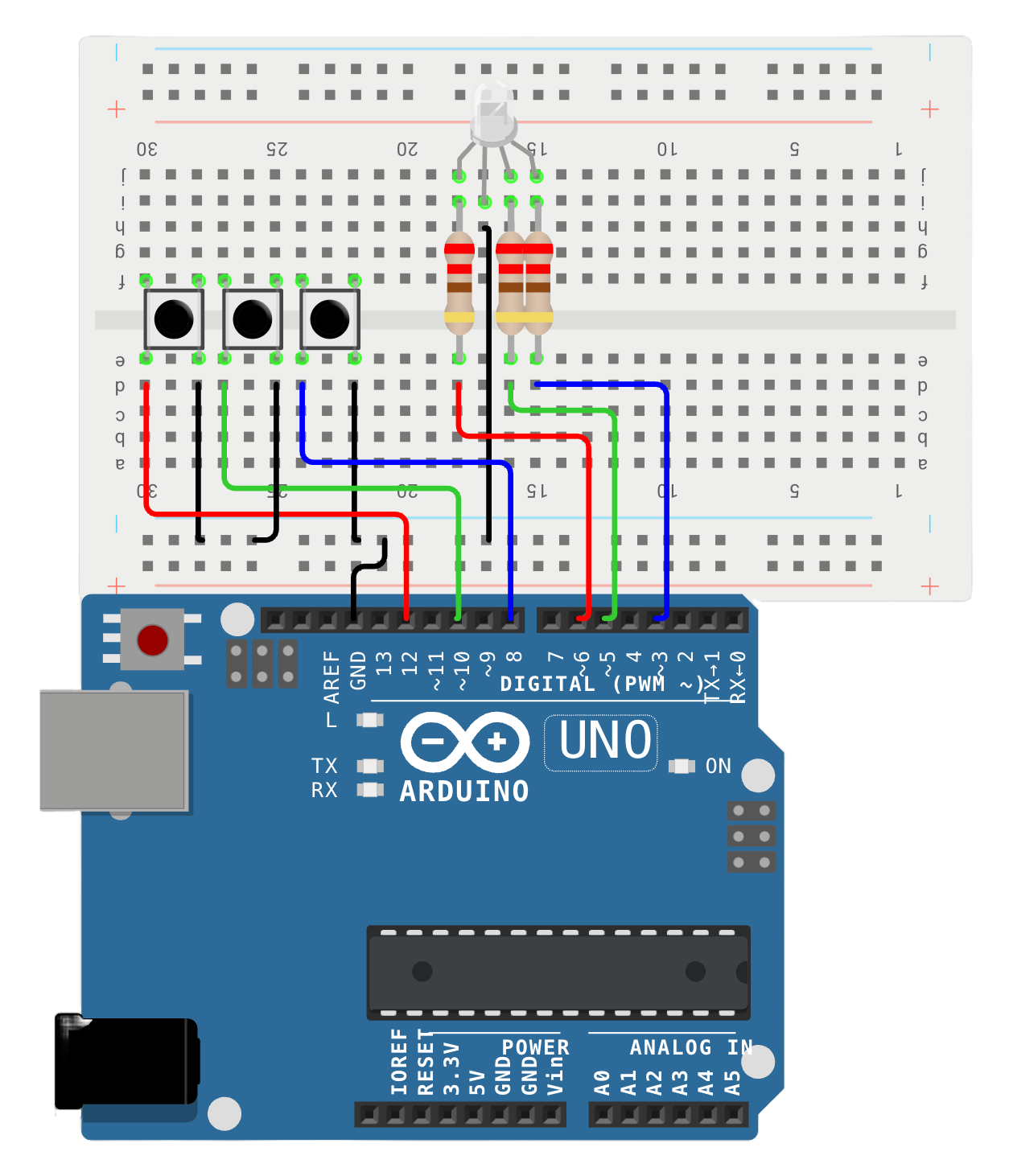
You can actually simulate this circuit on Wokwi, which is insanely cool. I really wanted to make a diagram and at first I wrestled with building Fritzing from source, but that was a dependency disaster and I opted for an online tool instead. Apparently there is ample, according to a quick Google search. I am hoping to move up to schematic diagrams once my electronics knowledge advances. For now they look like labyrinths.
The digital pins on the board supply the current to each of the components. I helpfully colour-coded them according to the code, red for red, green for green, and blue for blue. For the push switches I only need the pins to be digital, so they can be either high or low. For the LED however, I need the pins to be kind of analogue. The PWM ~ on the board stands for Pulse Width Modulation, and those pins marked with the tilde sign (~) can be used to achieve analogue results with digital means. What this means is that the pin can output a "high" for a fraction of a cycle - for example, if it's emitting high 20% of the time it will be outputting 20% of the full power.
Both the resistors and the push switches don't actually have to be stretching over the grand canyon in the middle, but it does help in terms of space and layout. Nonetheless, as long as the connectivity is vertical and the resistors are somewhere in the LED connection, the setup would still work. If you don't believe me you can try moving things around on Wokwi (again, coolest thing ever).
At the bottom of the breadboard there are the two rails, where 4 black wires are connected to the minus strip. This is the ground strip that allows the current to complete its circuit.
The code
The code for the Arduino is some stripped down version of C++. The built-in library is simple so far, and things like pinMode, digitalRead and digitalWrite are self-explanatory. Two functions are always required: the setup(), which sets up the hardware to be used in the circuit, and the loop() which executes some code indefinitely.
#define RED 6
#define GREEN 5
#define BLUE 3

#define buttonRpin 12
#define buttonGpin 10
#define buttonBpin 8

#define stepSize 1
#define delayTime 5

void setup() {
  pinMode(RED, OUTPUT);
  pinMode(BLUE, OUTPUT);
  pinMode(GREEN, OUTPUT);
  pinMode(buttonRpin, INPUT_PULLUP);
  pinMode(buttonBpin, INPUT_PULLUP);
  pinMode(buttonGpin, INPUT_PULLUP);
  digitalWrite(RED, LOW);
  digitalWrite(BLUE, LOW);
  digitalWrite(GREEN, LOW);
}

int redValue = 0;
int blueValue = 0;
int greenValue = 0;

void loop() {
  if (digitalRead(buttonRpin) == LOW) {
    redValue += stepSize;
    if (redValue == 255) {
      redValue = 0;
    }
    analogWrite(RED, redValue);
    delay(delayTime);
  }
  if (digitalRead(buttonBpin) == LOW) {
    blueValue += stepSize;
    if (blueValue == 255) {
      blueValue = 0;
    }
    analogWrite(BLUE, blueValue);
    delay(delayTime);
  }
  if (digitalRead(buttonGpin) == LOW) {
    greenValue += stepSize;
    if (greenValue == 255) {
      greenValue = 0;
    }
    analogWrite(GREEN, greenValue);
    delay(delayTime);
  }
}
The way this works to control the intensity and mixing of the RGB colours is as follows. The pins for the LED are first assigned, and set to low - this means they will be off when first powered. The push switch pins are set to INPUT_PULLUP, which means that while no signal is received, the voltage is set to high. This is useful here as we don't need an external pull-up resistor. The integer variables for each of the colours correspond to the intensity of the specific colour. Once the loop starts, as the buttons are pressed, their output is low, and the intensity of the specific colour increases by writing it to the correct pin. Once the analog signal becomes fully high, it is set to 0 again. The mixing is done by changing the intensity of different colours together, so high red and high blue would create purple, and high on all three would create white. The stepSize and delayTime are both used to create a smooth transition.
The real thing
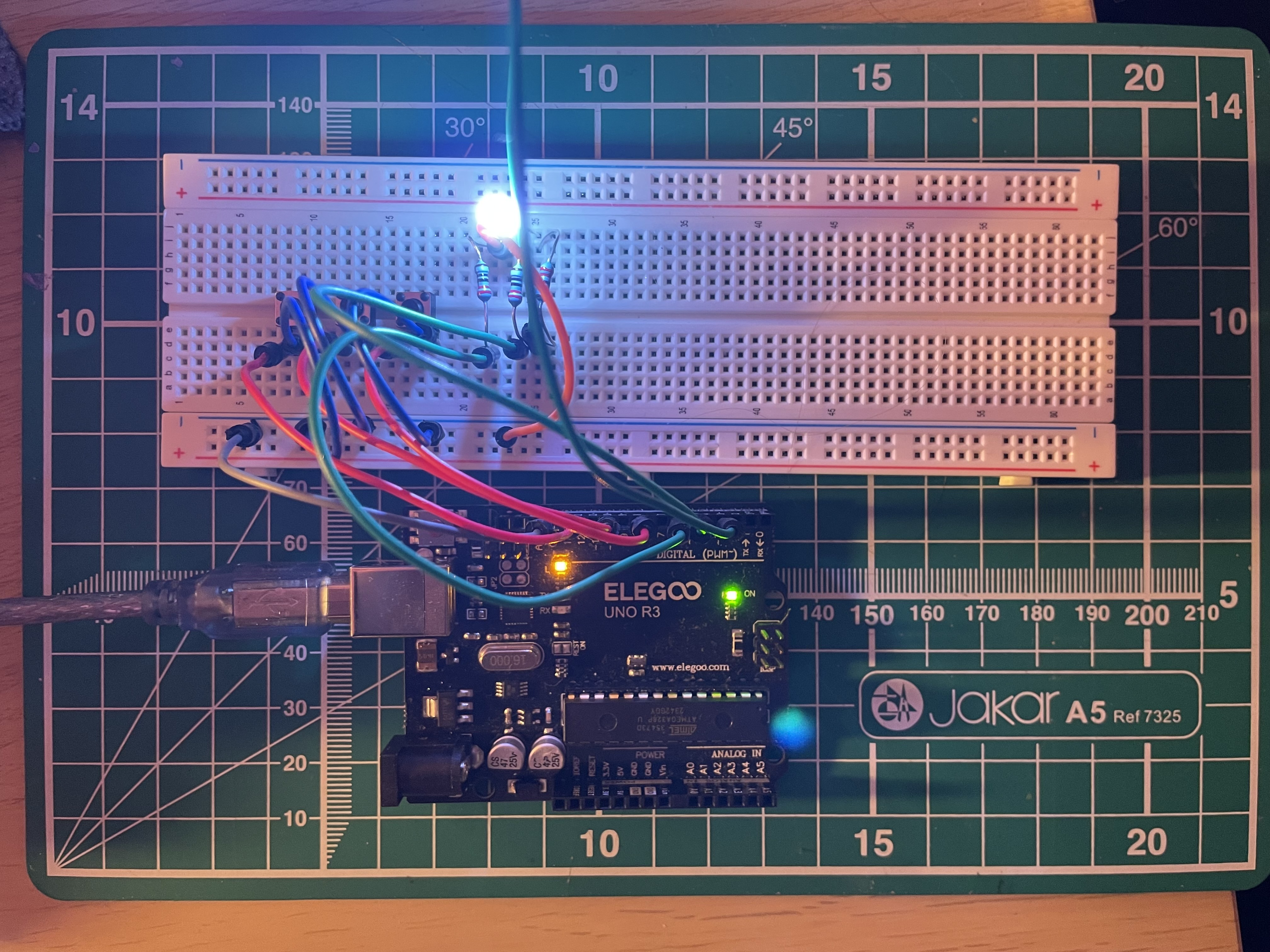
Possibly one of the most beautiful things I have ever personally seen. The wires are definitely more of a pain than the diagram might suggest, they are quite flimsy and they get in the way, but they get the job done. Assembly altogether takes very little time, and it is very satisfying – I love the fact that I can take out different wires and see what the immediate effect is, it has certainly helped with my understanding of the breadboard connectivity.
Ending thoughts
Truly, completely and absolutely I have loved doing this and I cannot wait to get through more lessons and build ever cooler things. I always try to tell anyone who will listen that code and technology allow people to be creative – I would not be surprised if two brain scans done on a tinkering and a painting person were more alike than different.
This was also my first ever blog post, just as this is my first ever website. I have had an enormous amount of fun creating it so far.